Automotive energy storage electrical system vehicle capacitors Onboard power solutions
Technical specification
Material |
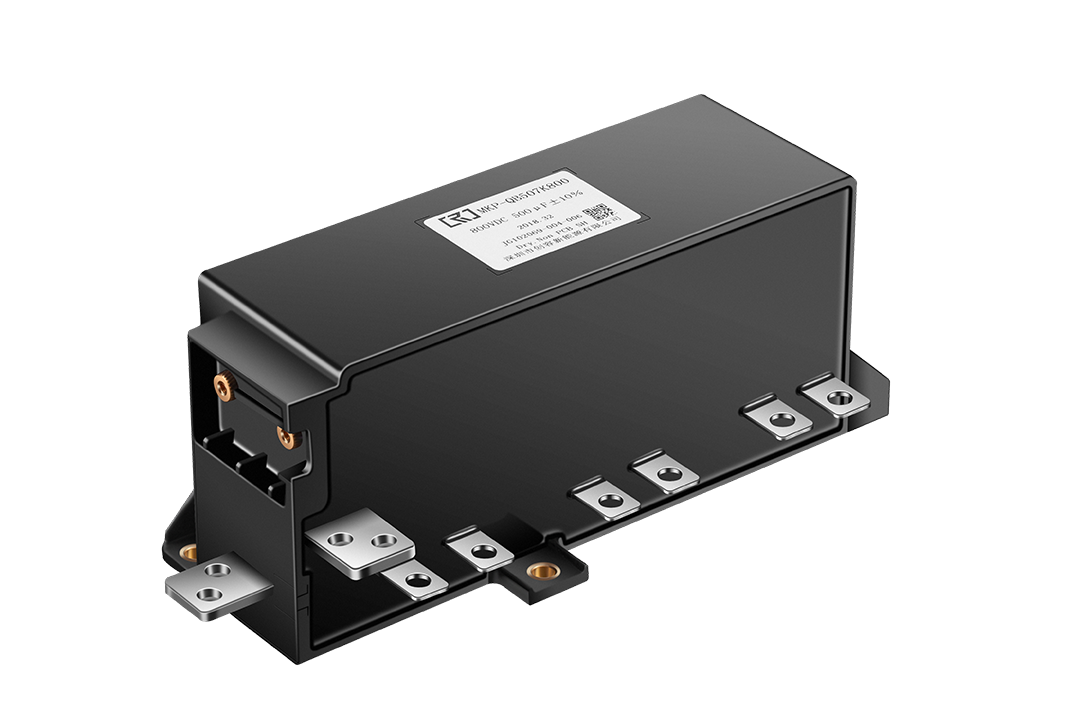
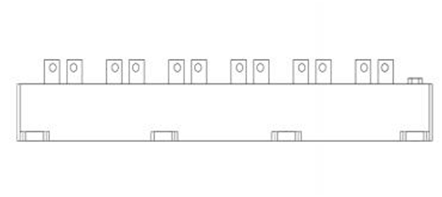
Outline |
|
Item |
Name |
|
Film |
Metallized Polypropylene Film |
|
Electrode |
Brass tinned/T2 Copper plate tinned |
|
Potting material |
Flame retardant black epoxy (epoxy resin)) |
|
Shell |
Plastic shell(PPS+GF55) |
|
Technical specification
Rated capacitance |
CN |
1000µF@100Hz ±5% |
Rated voltage |
UN |
700V.DC |
Surge voltage |
US |
800V.DC t<30mS |
Working frequency |
f |
10~20kHz |
|
Maximum allowable ripple current effective value (AC terminal) |
Irms |
400A(Continuous current@10KHz, Ambient temperature≤65℃) |
|
600A(≤30s@10KHz, Ambient temperature≤65℃ | ||
“+”、“- ”Pole rated DC current (average value, continuous) |
Idc |
100A(Continuous current@10KHz, Ambient temperature≤65℃) |
“+”、“- ”Maximum DC current (average value, short time) |
Idc |
150A(30s/30min, Ambient temperature≤65℃) |
|
Rated current flowing between the same pair of poles (average value, continuous) |
I |
40A(Continuous current@10KHz, Ambient temperature≤65℃) |
|
Peak current flowing between the same pair of poles (average, short time) |
I |
60A(30s/30min , Ambient temperature≤65℃) |
Maximum peak current |
Î |
2.2kA(t≤10μs,Intervals≥60s) |
Maximum surge current |
IS |
8.8kA(t<30ms/per 1000 次) |
Voltage change rate |
dv/dt |
>4V/μs |
Equivalent series resistance |
RS |
≤0.4mΩ(10kHz) |
Equivalent series resistance at end of life |
RS(EOL) |
≤0.6mΩ(10kHz) |
Dielectric loss angle |
tanδ |
≤0.0015(100Hz) |
Insulation resistance |
C×Ris |
>10000S 500VDC 60S |
Self-inductance Ls |
Le |
≤20nH@1MHz(Based on actual measurements) |
Minimum operating temperature |
Θmin |
-40℃ |
Maximum operating temperature |
Θmax |
105℃ |
Storage temperature |
Θstorage |
-40~+80℃ |
Expected lifespan |
△C/C<15% Rated operating conditions |
100000h (Refer to the life curve) |
Inefficiency |
|
<50Fit |
Test Conditions | ||
Interelectrode withstand voltage |
Vtt |
1050V.DC/10S |
Shell pressure resistance |
Vt-c |
3500V.AC/60S |
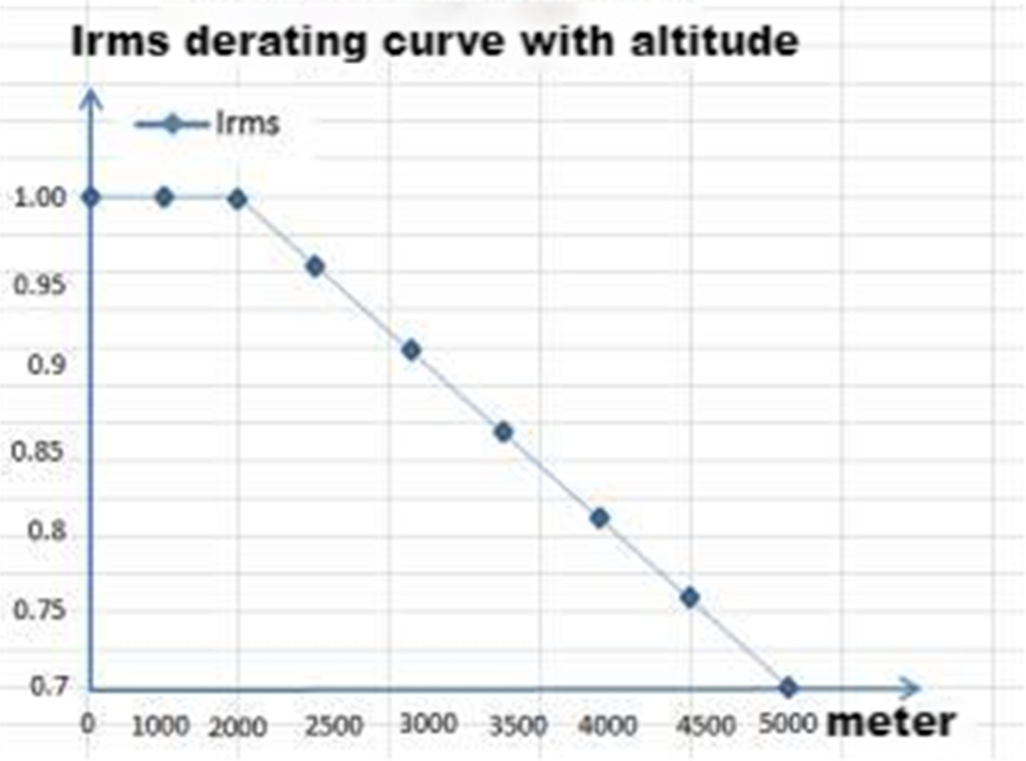
Maximum working altitude |
|
5000m (over 2000m, refer to derating curves) |
Housing mounting hole torque |
|
≤4N.m |
Maximum operating humidity |
|
40℃、 93RH% |
Note: If the altitude exceeds the specified value, derating is required (refer to the derating curve). | ||
Cover voltage |
1.1 UN (30% of on-load-dur.) @65℃ |
|
1 .15 UN (30min/day) @65℃ | ||
1.2 UN (5min/day) @65℃ | ||
1.3 UN (1min/day) @65℃ | ||
|
1.5 UN (30ms every time, 1 000times during the life of the capacitor)
| ||
General testing
No. |
Item |
performance |
Test conditions |
1 |
Visual inspection |
The product has no visible damage and the label is clear |
Visual |
2 |
Checking size |
Conforms to the drawings in the specification |
Gauges, Calipers, Gauges |
3 |
Interelectrode withstand voltage |
No permanent breakdown or flashover |
Automatic breakdown device (ABS) 1050Vdc,10s,25℃±5℃ |
4 |
Shell withstand voltage |
No permanent breakdown or flashover |
Automatic breakdown device (ABS) 3000Vac,50Hz,10s,25℃±5℃ |
5 |
Electric capacity |
J(±5%) |
LCR Measuring instrument 100Hz |
6 |
tanδ |
<15 x10-4 , 100Hz |
LCR Measuring instrument 100Hz |
7 |
Insulation resistance between poles |
RC≥10000s (MΩ) |
500Vdc,60s,25℃±5℃ |
8 |
Equivalent series resistance |
Comply with the technical parameters in the specification |
LCR Measuring instrument 10KHz |
Type test( IEC 61071, AEC Q200D-2010 )
No. |
Item |
Performance |
Test conditions |
1 |
Visual inspection |
The product has no visible damage and the label is clear |
Visual |
2 |
Inter-electrode withstand voltage |
No permanent breakdown or flashover |
Automatic breakdown device (ABS) 1050Vdc,60s,25℃±5℃ |
3 |
External shell withstand voltage |
No permanent breakdown or flashover |
Automatic breakdown device (ABS) 3000Vac,50Hz,60s,25℃±5℃ |
4 |
Capacitance |
J(±5%) |
RLC Measuring instrument 100Hz |
5 |
tanδ |
<15 x10-4 , 100Hz |
RLC Measuring instrument 100Hz |
6 |
Inter-electrode insulation resistance |
RC≥10000s (MΩ) |
500Vdc,60s,25℃±5℃ |
7 |
Equivalent series resistance |
Comply with the technical parameters in the specification |
RLC Measuring instrument 10KHz |
8 |
Mechanical stress (limited to products with nuts or screws) |
No visible damage to the threads |
Methods and specific test torque requirements GB/T 2423.60-2008 Test Ud15: Torque test |
Reliability testing
No. |
Item |
Performance |
Test conditions |
Conforms to the terms of the AEC-Q200 standard |
|
1 |
Vibration (special vehicle) |
All functions meet the design requirements. Working mode GB/T28046.1-2011 5.3 Working mode 3.2 |
50-500Hz sweep frequency, Each axis lasts for 8 hours, Acceleration is 5g; (The whole machine has vibration damping) |
No such clause |
2 |
Shock |
All functions meet the design requirements. Working mode GB/T28046.1-2011 5.3 Working mode 3.2 |
Acceleration is 15g (transient, 100ms); (The whole machine has vibration damping cushion) |
No such clause |
3 |
Impulse Discharge Test |
No permanent breakdowns or flashes ︱△C/C0 ︱≤1% |
5 charges and discharges in 10 minutes; Test voltage: 1.1UN; Test current: 1.1 times the maximum inrush current; Inter-pole withstand voltage test within 5 minutes after the test; |
No such clause |
4 |
Temperature cycle |
No visible damage, clear markings ︱△C/C0 ︱≤2% |
Test method see AEC-Q200 Table 4 Tmin=-40℃±2℃ Dwell time ≤30min Tmax=+105℃±2℃ Dwell time ≤30min Switching time ≤1min Cycle times: 100 times |
AEC-Q200 Excel No4 |
5 |
Low temperature storage |
No visible damage︱△C/C0 ︱≤2% |
Test temperature: -40℃±2℃ Time: 48h Non-operating state, recovery under standard test conditions for 24h |
No such clause |
6 |
High temperature storage |
No visible damage︱△C/C0 ︱≤2% |
Test temperature: 105℃±2℃ Time: 48h Non-operating state Recovery under standard test conditions for 24h |
AEC-Q200 Excel 4 No3 |
7 |
Moisture load resistance |
No visible damage︱△C/C0 ︱≤3% △ESR/ESR≤50% RC≥5000s |
Test method see MIL-STD-202 method 103 Temperature: 40℃±2℃ Humidity: 93%+2-3 RH Duration: 500h Test voltage: Un |
AEC-Q200 Excel 4 No7 |
8 |
Durability test |
No visible damage, clear markings ︱△C/C0 ︱≤3% △ESR/ESR≤50% RC≥5000s |
Temperature: 105℃±3℃ Applied voltage: Un Test time: 1000h |
AEC-Q200 Excel 4 No8 |
9 |
Thermal stability experiment |
︱△T︱≤1K |
Applied current: Irms; Experimental time: ≥48h; In the last 6h, 4 measurements were performed, and the temperature rise should not exceed 1K |
No such clause |
10 |
Rated current test |
Product temperature rise≤20 °C ︱△C/C0 ︱≤2% |
Temperature: 65℃±3℃ Applied current: Irms Test time: 6h |
No such clause |
Derating curve: