
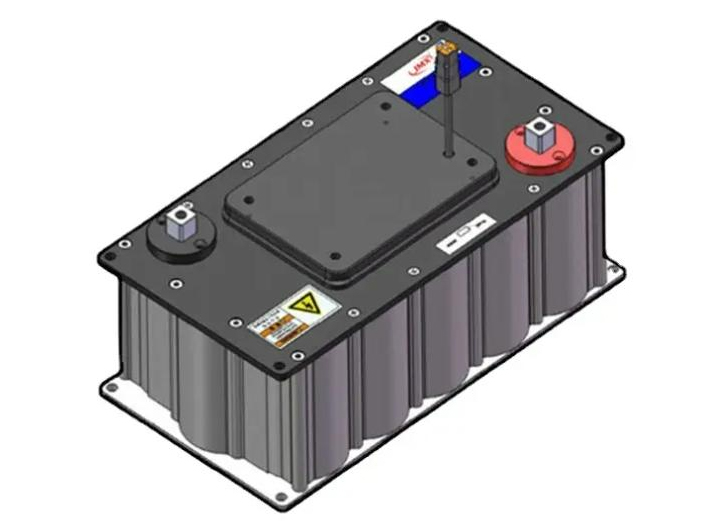
Automotive energy storage electrical system vehicle capacitors Onboard power solutions
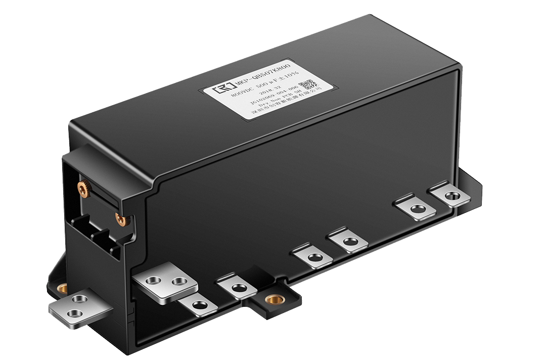
MKP-QB Series
|
Model |
800V/500uF
|
Parameters
|
Imax=150A(10Khz) |
AEC-Q200 |
Ls ≤ 12nH (1MHz) |
IEC61071:2017 |
|||
-40~105℃ |
|
|||
|
Features |
High ripple current capability high withstanding voltage capability |
|||
|
Compact size, low ESL. | ||||
|
Safety film design with self-healing properties. | ||||
|
Applications |
DC filiter circuits. |
|||
|
Electric and hybrid passenger vehicles. | ||||
Capacitor charging and discharging
General testing
No. |
Item |
performance |
Test conditions |
1 |
Visual inspection |
The product has no visible damage and the label is clear |
Visual |
2 |
Checking size |
Conforms to the drawings in the specification |
Gauges, Calipers, Gauges |
3 |
Interelectrode withstand voltage |
No permanent breakdown or flashover |
Automatic breakdown device (ABS) 1050Vdc,10s,25℃±5℃ |
4 |
Shell withstand voltage |
No permanent breakdown or flashover |
Automatic breakdown device (ABS) 3000Vac,50Hz,10s,25℃±5℃ |
5 |
Electric capacity |
J(±5%) |
LCR Measuring instrument 100Hz |
6 |
tanδ |
<15 x10-4 , 100Hz |
LCR Measuring instrument 100Hz |
7 |
Insulation resistance between poles |
RC≥10000s (MΩ) |
500Vdc,60s,25℃±5℃ |
8 |
Equivalent series resistance |
Comply with the technical parameters in the specification |
LCR Measuring instrument 10KHz |
Type test( IEC 61071, AEC Q200D-2010 )
No. |
Item |
Performance |
Test conditions |
1 |
Visual inspection |
The product has no visible damage and the label is clear |
Visual |
2 |
Inter-electrode withstand voltage |
No permanent breakdown or flashover |
Automatic breakdown device (ABS) 1050Vdc,60s,25℃±5℃ |
3 |
External shell withstand voltage |
No permanent breakdown or flashover |
Automatic breakdown device (ABS) 3000Vac,50Hz,60s,25℃±5℃ |
4 |
Capacitance |
J(±5%) |
RLC Measuring instrument 100Hz |
5 |
tanδ |
<15 x10-4 , 100Hz |
RLC Measuring instrument 100Hz |
6 |
Inter-electrode insulation resistance |
RC≥10000s (MΩ) |
500Vdc,60s,25℃±5℃ |
7 |
Equivalent series resistance |
Comply with the technical parameters in the specification |
RLC Measuring instrument 10KHz |
8 |
Mechanical stress (limited to products with nuts or screws) |
No visible damage to the threads |
Methods and specific test torque requirements GB/T 2423.60-2008 Test Ud15: Torque test |
C: Reliability testing
| No. | Item | Performance | Test conditions | Conforms to the terms of the AEC-Q200 standard |
| 1 |
Vibration (special vehicle) |
All functions meet the design requirements. Working mode GB/T28046.1-2011 5.3 Working mode 3.2 |
50-500Hz sweep frequency, Each axis lasts for 8 hours, Acceleration is 5g; (The whole machine has vibration damping) |
No such clause |
| 2 | Shock |
All functions meet the design requirements. Working mode GB/T28046.1-2011 5.3 Working mode 3.2 |
Acceleration is 15g (transient, 100ms); (The whole machine has vibration damping cushion) |
No such clause |
| 3 | Impulse Discharge Test | No permanent breakdowns or flashes ︱△C/C0 ︱≤1% |
5 charges and discharges in 10 minutes; Test voltage: 1.1UN; Test current: 1.1 times the maximum inrush current; Inter-pole withstand voltage test within 5 minutes after the test; |
No such clause |
| 4 | Temperature cycle | No visible damage, clear markings ︱△C/C0 ︱≤2% |
Test method see AEC-Q200 Table 4 Tmin=-40℃±2℃ Dwell time ≤30min Tmax=+105℃±2℃ Dwell time ≤30min Switching time ≤1min Cycle times: 100 times |
AEC-Q200 Excel No4 |
| 5 | Low temperature storage | No visible damage︱△C/C0 ︱≤2% |
Test temperature: -40℃±2℃ Time: 48h Non-operating state, recovery under standard test conditions for 24h |
No such clause |
| 6 | High temperature storage | No visible damage︱△C/C0 ︱≤2% |
Test temperature: 105℃±2℃ Time: 48h Non-operating state Recovery under standard test conditions for 24h |
AEC-Q200 Excel 4 No3 |
| 7 | Moisture load resistance |
No visible damage︱△C/C0 ︱≤3% △ESR/ESR≤50% RC≥5000s |
Test method see MIL-STD-202 method 103 Temperature: 40℃±2℃ Humidity: 93%+2-3 RH Duration: 500h Test voltage: Un |
AEC-Q200 Excel 4 No7 |
| 8 | Durability test |
No visible damage, clear markings ︱△C/C0 ︱≤3% △ESR/ESR≤50% RC≥5000s |
Temperature: 105℃±3℃ Applied voltage: Un Test time: 1000h |
AEC-Q200 Excel 4 No8 |
| 9 | Thermal stability experiment |
︱△T︱≤1K |
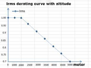
Applied current: Irms; Experimental time: ≥48h; In the last 6h, 4 measurements were performed, and the temperature rise should not exceed 1K |
No such clause |
| 10 | Rated current test |
Product temperature rise≤20 °C ︱△C/C0 ︱≤2% |
Temperature: 65℃±3℃ Applied current: Irms Test time: 6h |
No such clause |
Tests